
Residential Covered Breezeway Addition · New Smyrna Beach, FL
Covered Breezeway Architectural & Structural Plans — New Smyrna Beach, FL
Prepared an eight-sheet architectural and structural drawing package for a proposed 42′ × 9′ covered breezeway connecting an existing casita and detached metal building in New Smyrna Beach, Florida. The plans documented the site layout, reinforced-concrete foundation, CMU wall and columns, roof framing, building elevations, and structural connections.
 Project executed and assisted byEngineer Wasim
Project drawings and images.
View-only. Select an image to enlarge, or page through the drawing set below.
Drawings and images are shown for viewing only. Client details are removed and the work is shown with the client's permission.
The challenge.
The proposed breezeway needed to connect two existing structures with different building configurations while maintaining a consistent covered passage and addressing the structural demands of Florida construction.
The project required coordination with an existing 34′ × 34′ metal building and a separate casita. The proposed breezeway was approximately 42 feet long and 9 feet wide, with a corrugated metal roof and a reinforced masonry support system.
One of the primary challenges was defining an appropriate foundation arrangement for the proposed reinforced CMU columns and rear wall. The drawings needed to document a monolithic slab-on-grade with integral thickened edges and appropriate footing details rather than relying on an undefined concrete slab.
The roof design also required careful attention. Connection details needed to account for the differences between the two existing structures, roof drainage, flashing and weatherproofing, and the transfer of gravity and wind-uplift forces through the supporting elements.
Additional considerations included providing two door openings in the rear CMU wall, documenting the proposed roof slope, coordinating the breezeway finished-floor elevation with the existing metal building, and distinguishing the covered breezeway scope from a potential future outdoor kitchen and bar.
The challenge was to bring these architectural, foundation, framing, and connection requirements together into one coherent drawing set.
Our approach.
We developed an eight-sheet drawing package organizing the proposed breezeway into site, architectural, structural, and construction-detail components.
**1. Property Site Planning**
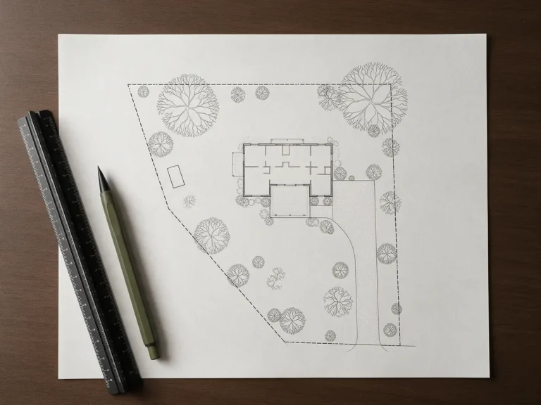
The site plan documented the existing residential property, relevant parcel features, existing buildings, and proposed breezeway placement. The design showed the new covered connection between the casita and detached metal building.
**2. Breezeway Layout**
The proposed floor plan documented the 42′ × 9′ breezeway, including its approximately 378-square-foot area, relationship to the two existing buildings, and placement of the reinforced CMU support elements.
**3. Building Elevations and Sections**
Architectural elevations and cross-sections illustrated the proposed roof geometry, building heights, masonry support system, roofing components, and connections to the existing structures.
**4. Monolithic Slab and Foundation Documentation**
The structural drawings included a reinforced-concrete slab-on-grade system, integral thickened edges, column footing references, and details supporting the proposed reinforced masonry construction.
**5. Reinforced Masonry Wall and Columns**
The plans illustrated an 8-inch reinforced CMU rear wall and 16-inch by 16-inch reinforced, fully grouted CMU columns. Related details addressed reinforcement and connections to adjoining construction.
**6. Roof Framing Design Documentation**
The roof framing drawings identified the proposed roof slope, rafter spacing, beam layout, roof sheathing, roofing assembly, and hurricane connector requirements.
**7. Connections and Weatherproofing**
The drawing set included connection and flashing notes at the existing buildings, including a super-gutter detail at the breezeway-to-casita interface. The plans also specified that attachments should transfer loads to appropriate structural elements rather than relying on exterior cladding alone.
**8. Construction Notes and Coordination**
The cover sheet and structural notes addressed material requirements, verification of existing dimensions and elevations, foundation preparation, construction sequencing, code references, and structural load-path considerations.
The completed package assembled the main information needed for further design review and permit coordination into a structured architectural and structural drawing set.
The outcome.
An eight-sheet architectural and structural drawing package was prepared for the proposed residential breezeway addition.
The drawings documented the new 378-square-foot covered connection between the existing metal building and casita, including the site layout, proposed floor plan, exterior elevations, cross-sections, monolithic slab foundation, reinforced masonry supports, roof framing, and construction details.
The package also coordinated important project-specific features such as the existing structure interfaces, roof flashing and drainage, masonry wall openings, foundation support, and Florida wind-load connection considerations.
This case study demonstrates the level of coordination involved when designing a seemingly simple covered passage between existing buildings. By organizing the architectural and structural requirements into separate drawing sheets, the project provided a clearer basis for technical review and continued permit coordination.
Final permit approval, field verification, and completed construction have not been independently verified.
This residential construction project involved preparing a coordinated architectural and structural drawing package for a proposed 378-square-foot covered breezeway in New Smyrna Beach, Volusia County, Florida.
The proposed 42-foot-long by 9-foot-wide breezeway was designed to connect an existing 34-foot by 34-foot metal building with an existing casita, creating a covered connection between the two structures.
The design incorporated a monolithic reinforced-concrete slab-on-grade, reinforced concrete masonry columns, an 8-inch reinforced CMU rear wall, engineered roof framing, and corrugated metal roofing with a documented 3:12 roof slope.
The drawing package addressed site placement, foundation and slab construction, building elevations, wall and column reinforcement, roof framing, and structural connections to the existing buildings. Special attention was given to the connection between the new breezeway roof and the existing structures, including flashing, drainage, and the continuous load path needed to address Florida wind conditions.
The eight-sheet package was prepared for client and permitting coordination. Final construction approval, structural acceptance, and completion of the proposed work have not been independently verified.
Need Permit Drawings for a Breezeway, Patio Cover or Building Addition?
Whether you’re connecting two existing structures, adding a covered walkway, or planning a new outdoor improvement, Deck Permit Plans can help prepare coordinated site, architectural, structural, foundation, and roof framing drawings for your project.
Send us your property survey, existing drawings, photographs, proposed dimensions, and any city or county permit comments.
Sheets in the set.
Services used on this project.
 Site PlansProperty lines, structures, setbacks and the proposed work, drawn to scale for permit review.View details
 Permit Drawing SetsCoordinated sheets organized as one package for permit submission.View details
 Architectural PlansFloor plans, elevations, sections and roof plans for your project.View details
 Structural PlansFraming, foundation and connection details for the proposed structure.View details
More case studies.
- Proposed Two-Story Attached Accessory Dwelling Unit · Harbor City, Los Angeles, CATwo-Story Attached ADU Permit Plans — Harbor City, CaliforniaPrepared a 16-page architectural, structural, and MEP drawing package for a proposed 805 sq. ft. two-story attached ADU in Harbor City, California. The plans documented site placement, residential layouts, building elevations, foundation and framing systems, electrical and plumbing services, and applicable construction details.Read the case study
- Storm-Damaged Roof & Exterior Wall Structural Repair · Flossmoor, IllinoisStorm-Damaged Roof & Exterior Wall Repair Plans — Flossmoor, IllinoisPrepared a four-page residential drawing package for storm-related roof and exterior wall repairs in Flossmoor, Illinois. The documentation included an existing 5,441 sq. ft. roof plan, exterior elevations, general repair notes, and identification of the areas affected by tree-impact damage.Read the case study
- Shipping Container Art Studio — Residential Accessory Structure · Kailua-Kona, HawaiiShipping Container Art Studio Permit Plans — Kailua-Kona, HawaiiPrepared an 18-sheet architectural, structural, and MEP drawing package for a proposed 20′ × 8′ shipping-container art studio on an existing residential property in Kailua-Kona, Hawaii. The project included site planning, container anchorage and foundation documentation, interior studio layout, electrical service, HVAC and kiln exhaust, and plumbing details.Read the case study
Planning a similar project?
Send the address and what you are building. We reply with the scope, price and timeline.